CNC machine, full name Computer Numerical Control machine, is a machine tool controlled by computer program and capable of precision machining. Traditional machine tools require manual operation, while CNC machines are operated by computers automatically according to preset programs, greatly improving production efficiency and precision.
📌 Common types of CNC machines:
| Type | Function | Scope of application |
|---|---|---|
| CNC lathe | Rotating workpiece, tool movement | Circular parts processing |
| CNC milling machine | Fixed workpiece, tool rotation cutting | Plane, hole processing |
| CNC Machining center | Multi-axis automatic tool change function | Complex parts, multi-faceted processing |
| CNC laser cutting machine | Laser cutting materials | Metal sheets, acrylic, etc. |

Operation principle of CNC machine:
- 1. Computer program:The operation of CNC machine is based on a pre-written computer program, which contains instructions such as processing path, tool selection, cutting speed, feed speed, etc.
- 2. Numerical control:The computer program converts these instructions into numerical signals and transmits them to the machine’s servo system to control the movement of each axis and achieve precise processing.
- 3. Automated processing: Through computer program control, CNC machines can automatically complete complex processing actions, such as turning, milling, drilling, boring, etc., without human intervention.
Advantages of CNC machines:
- High precision: : Computer control can achieve extremely small tolerances to ensure product accuracy and consistency.
- High efficiency:: Automated processing, reduce manual intervention, improve production efficiency.
- High flexibility:: The program can be modified, which is convenient and fast to switch different processing tasks, suitable for multi-variety and small batch production.
- Reduced cost:: Reduce labor cost and material waste, and reduce production cost.
- Complex processing:: It can complete complex shapes and curved surface processing that are difficult to achieve with traditional machines.
🔧 Important parameters in CNC operation:
-
- Spindle speed (RPM): Tool rotation speed
-
- Feed rate (Feed Rate) : Feed rate of the tool
-
- Depth of Cut : Depth of each cut
-
- Coolant control : Prevent tool overheating and processing deformation
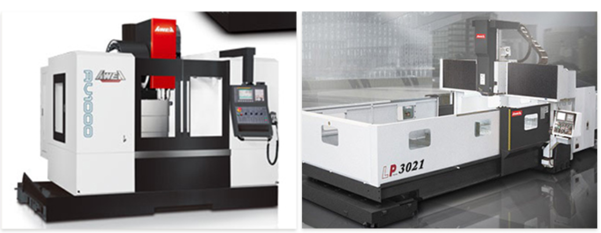
The following is the description, process and sample G-code of our company using Yawei gantry machining center LP-3021 for metal material processing.
🏭 Machine Overview and Material Adaptation
LP‑3021 Main Parameters (Three-axis type)chanpin.gongchang.com+11xyh-cnc.com+11awea.com+11:
-
- X / Y / Z travel: 3,000×2,100×760mm
-
- Workbench size: 3,020×2,010mm, maximum load capacity up to 10,000kg
-
- Spindle power: 22kW (continuous), 26kW (30 minutes)
-
- Spindle speed: standard 6,000rpm (optional direct drive to 8,000~12,000rpm)
-
- Rapid moving rate: X = 20,000mm/min; Y / Z = 15,000mm/min
-
- Accuracy: Positioning ±0.015mm, full-range repeatability ±0.003mm
Material of machine structure:
-
- Base and gantry adopt Meehanite Cast iron (Meehanite), heat treated and finely ground, with extremely high rigidity and vibration resistanceScribd+9awea.com+9awea.com+9Scribd+8awea.com+8awea.com+8awea.com+6m.zgong.com+6China Manufacturing Network+6Scribd+1awea.com+1。
Suitable processing materials:
<!– wp:list –>
<ul class=”wp-block-list”><!– wp:list-item –>
<li>Aluminum alloy, carbon steel, stainless steel, tool steel, plastic, etc. If you start with aluminum alloy (such as 6061-T6), you can get a faster learning curve and good tool life. </li>
<!– /wp:list-item –></ul>
<!– /wp:list –>
<!– wp:separator –>
<hr class=”wp-block-separator has-alpha-channel-opacity”/>
<!– /wp:separator –>
<!– wp:heading –>
<h2 class=”wp-block-heading”>⚙️ Process example: Processing an aluminum alloy block</h2>
<!– /wp:heading –>
<!– wp:paragraph –>
<p><strong>Workpiece specifications</strong>: 100×100×50mm aluminum block, processed from the original size (100×100×50, leaving tolerance allowance) to the size of 80×80×40 mm. </p>
<!– /wp:paragraph –>
<!– wp:paragraph –>
<p><strong>Tool selection</strong>:</p>
<!– /wp:paragraph –>
<!– wp:list –>
<ul class=”wp-block-list”><!– wp:list-item –>
<li>Rough cutting: D20mm endmill for aluminum</li>
<!– /wp:list-item –>
<!– wp:list-item –>
<li>Fine machining: D10mm endmill</li>
<!– /wp:list-item –></ul>
<!– /wp:list –>
<!– wp:paragraph –>
<p><strong>Cutting conditions (aluminum)</strong>:</p>
<!– /wp:paragraph –>
<!– wp:list –>
<ul class=”wp-block-list”><!– wp:list-item –>
<li>Roughing: spindle 8,000 rpm, feed 3,200 mm/min, depth of cut ap=5 mm, width ae=10 mm</li>
<!– /wp:list-item –>
<!– wp:list-item –>
<li>Fine cutting: spindle 10,000 rpm, feed 2,500 mm/min, depth of cut ap=1 mm, ae=0.5 mm</li>
<!– /wp:list-item –></ul>
<!– /wp:list –>
<!– wp:separator –>
<hr class=”wp-block-separator has-alpha-channel-opacity”/>
<!– /wp:separator –>
<!– wp:heading –>
<h2 class=”wp-block-heading”>✍️ Example G‑code</h2>
<!– /wp:heading –>
<!– wp:preformatted –>
<pre class=”wp-block-preformatted”>gcode copy and edit<code>%
O1000 (LP-3021 aluminum alloy cube processing example)
(Roughing – Rough material removal to shape + height)
T1 M6 (20mm Endmill)
S8000 M3
G54
G0 X0 Y0 Z100
M8
G0 X50 Y50
G1 Z5 F3200
(Roughing contour path)
G1 X150 F3200
G1 Y150
G1 X50
G1 Y50
G0 Z100
(Finishing)
T2 M6 (10mm Endmill)
S10000 M3
G0 X50 Y50 Z100
G1 Z5 F2500
(fine contour)
G1 X130 Y50
G1 Y130
G1 X50
G1 Y50
G0 Z100
M9
G0 X0 Y0
M30
%
Explanation steps
- Set tool and spindle: T1→T2, select end mills of different diameters according to the processing stage.
- Rapid positioning:
G0Enter the top of the workpiece from the safe height. - Roughing: Cutting with high-speed straight lines to remove excess shapes.
- Finishing: Use smaller tools and fine cutting conditions to achieve the final size.
- End tool cleaning and return to origin:
M9turns off the coolant,M30ends the program.
📐 Precautions and parameter recommendations
- Workpiece origin can be defined by G54 at the workpiece center (50,50), or set as usual at the lower left corner.
- Spindle mode uses direct-connection type to improve aluminum processing performance and surface quality.
- The machine has automatic compensation, spindle temperature control, load feed adjustment and other functions, which can improve processing stability and tool life.
- Coolant It is recommended to start
M8. Aluminum processing usually uses oil mist or emulsion to help heat dissipation and chip removal. - If more complex five-sided processing (such as holes and five-sided chamfers) is required, the LP‑3021 can be used with a vertical or horizontal exchange head library and generate G‑code with A/C axes through CAM.
Next, the following is an advanced G-code example for stainless steel processing on the “Yawei LP-3021 Gantry Machining Center”, including:
🎯 Processing Target
Using SUS304 as the material, a workpiece with a size of 100×100×40mm is processed, including:
| Processing items | Description |
|---|---|
| Drilling | Ø10 mm through hole, position (X30, Y30) |
| Eccentric hole | Ø15 mm hole, center offset to (X70, Y30) |
| Chamfering | Chamfering the four sides of the upper surface 1 mm |
| Five-sided processing | Upper plane and four side vertical surfaces are all milled flat |
| Material | SUS304 stainless steel (difficult to process material) |
| Tool | High hardness tungsten steel end mill, special alloy drill |
🧰 Processing settings (applicable to stainless steel)
- Tool material: Tungsten steel (Coated Carbide with TiAlN coating)
- Tool life considerations: Coolant and stable feed are required
- Processing parameter recommendations:
- Spindle speed: 1,200 to 2,000 rpm
- Feed rate: 100-300 mm/min (depending on diameter/tool)
- Deep hole machining: G83 plus G73 (chip removal cycle drilling)
✍️ G-code example (based on FANUC Based on)
gcode copy edit%
O2000 (SUS304 five-sided processing + drilling + chamfering)

(Workpiece: 100x100x40 SUS304)
G90 G21 G17 G40 G49 G80 G54
T1 M6 (Ø20 face milling cutter - side processing)
S1800 M3
M8

(Processing the upper plane)
G0 X0 Y0 Z100
G0 Z5
G1 Z-1 F150
G1 X100 Y0 F250
G1 Y100
G1 X0
G1 Y0
G0 Z100

(Processing the right side)
G0 X100 Y0 Z5
G1 Z-40 F150
G1 Y100
G0 Z100

(Processing the left side)
G0 X0 Y0 Z5
G1 Z-40 F150
G1 Y100
G0 Z100

(Processing the front and back sides is similar...)

---

(Switch Ø10mm drill - drilling)
T2 M6
S1200 M3
G0 X30 Y30 Z100
G83 Z-45 R5 Q2.5 F120 (through drilling, 45mm deep, 2.5mm step)
G80
G0 Z100

(eccentric hole Ø15mm)
T3 M6 (Ø15mm drill)
S1100 M3
G0 X70 Y30 Z100
G83 Z-45 R5 Q2.5 F100
G80
G0 Z100

---

(Chamfering, using 45° chamfering tool Ø10mm)
T4 M6
S2000 M3
G0 X5 Y5 Z5
G1 Z-1 F120
G1 X95
G1 Y95
G1 X5
G1 Y5
G0 Z100

M9
G0 X0 Y0
M30
%
🔍 Description of each paragraph:
| Command | Function |
|---|---|
G83 |
Deep hole periodic drilling with chip removal design |
G80 |
End periodic drilling |
R5 |
Quickly descend to a safe height |
Q2.5 |
Cutting 2.5 mm each time |
Z-45 |
Drill through 40mm plate thickness + allowance |
| Chamfering path | Can be changed to G1 X... Continuous four-side chamfering |
M8 |
Coolant on (necessary!) |
📌 Tool and safety reminder (SUS304 processing)
- Drills should be selectedSuperhard alloy, TiAlN coating, 135° Drill angle design
- When machining deep holes, be sure to use the periodic chip removal command (G83)
- Use tool length compensation (
G43 Hxx) and the correct tool length table (can be used with a tool setting instrument) - If you need to rotate the A/B axis when machining five sides, you can connect an external swing head or CNC indexing plate
- Coolant must be used during steel processing to extend tool life and prevent deformation
#CNC machine #Gantry machining center #G-code instruction table #Chamfering machining path #Drilling cycle instruction G83 #Stainless steel cutting parameters #CNC programming example
#Machining center five-sided machining #Face milling cutter / end milling cutter #End machining / chamfering machining #Tool setting / tool change instruction
#CNC Machining #CNC Milling #CNC Drilling #G-code Programming #CAM Software #CNC Toolpath #CNC Setup #Tool Offset / Work Offset (G54–G59) #Surface Milling / Face Milling #Contour Milling #Pocket Milling #Peck Drilling / Deep Hole Drilling #Chamfering #Boring / Reaming #Ta Cyclepping #Coolant Control (M8 / M9) #Feedrate / Spindle Speed Calculation
#Awea LP-3021 #Awea Gantry Type Machining Center #FANUC CNC Controller #FANUC G-code List #M-code List FANUC #G43 Tool Length Compensation #G83 Peck Drilling Cycle #G71/G72 Rough/Finish Turning (for lathes only) #CNC Axis Configuration (XYZ / 5-Axis)
#Aluminum alloy #6061 #7075 #Aluminum Machining Parameters #High Speed Milling Aluminum #Aluminum Endmill #Minimal Quantity Lubrication (MQL) #Chip Evacuation in Soft Metals
# stainless steel #SUS304 #316 #Stainless Steel Machining #SUS304 Machining Feedrate #TiAlN Coated Endmill #Peck Drilling Stainless #Heat-Resistant Alloy Machining #Cutting Force in Steel #Tool Wear in Hard Materials
#Carbide Endmill for Steel #Indexable Milling Tool #High Feed Milling #Radial / Axial Depth of Cut (ae / ap) #Toolpath Optimization #Tool Life Management #Cutting Fluid Selection #Vibration Reduction in Machining #Step Over / Step Down in Milling