
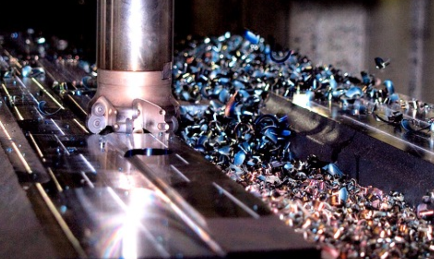
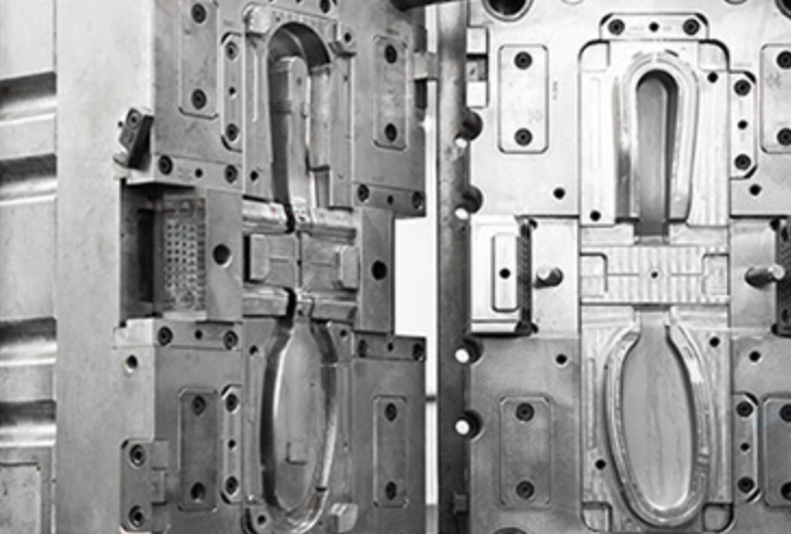
CNC machining process: G-code writing examples for aluminum alloy 3D parts and plastic molds
🧭 1. Initial Preparation Stage
1. Design Drawings (CAD)
Use CAD software (e.g., AutoCAD, SolidWorks, Fusion 360) to create 2D or 3D part drawings.
The drawings should clearly indicate dimensions, tolerances, materials, and other technical details.
2. Process Planning and Analysis
- Determine the machining sequence (e.g., roughing → semi-finishing → finishing).
- Select appropriate machining equipment (e.g., CNC lathe, milling machine, machining center).
- Choose suitable tools, fixtures, and coolants based on the material and design requirements.
🧮 2. Programming Stage
3. CAM Programming (Computer-Aided Manufacturing)
- Use CAM software (e.g., Mastercam, UG NX, Fusion 360) to generate toolpaths based on the CAD model.
- Set machining parameters such as spindle speed, feed rate, and depth of cut.
- Generate CNC machining code (G-code / NC code).
4. Simulation and Verification
- Perform virtual simulation using CAM software or directly on the CNC machine.
- Check for potential issues such as tool collisions, overcuts, and interference problems.
🏗️ 3. Machine Setup Stage
5. Equipment Setup and Calibration
- Install tools and apply tool length and radius offsets.
- Mount fixtures and securely clamp the workpiece.
- Set up the work coordinate system (e.g., G54, G55, etc.).
- Transfer the NC program to the CNC controller.
🛠️ 4. Actual Machining Stage
6. Machining Operation
- Perform a dry run or trial cut to verify the program is correct.
- Start the actual machining process under operator supervision.
- Monitor for tool wear, coolant flow, abnormal sounds, and any unexpected behavior during cutting.
🔍 5. Inspection and Post-Processing Stage
7. Quality Inspection
- Use measuring instruments (e.g., calipers, coordinate measuring machines) to check part dimensions, tolerances, and geometric accuracy.
- Confirm that all critical dimensions meet specifications.
8. Surface and Post-Processing (As Required)
- Processes may include deburring, grinding, sandblasting, anodizing, electroplating, etc.
9. Cleaning, Packaging, and Shipping
- Clean the finished parts to remove cutting fluids and burrs.
- Package, label, and ship according to customer requirements.
✅ Simplified CNC Machining Workflow Diagram:
mathematica複製編輯Design Drawing → Process Planning → Program Generation → Machine Setup → Trial Run & Verification → Machining → Quality Check → Surface Treatment → Shipping
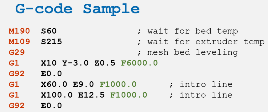
✳️ 1. G-code Examples and Explanation
G-code (also known as numerical control code) is the programming language used by CNC machines to execute machining operations. Common commands include:
Command Function Description
G00 Rapid movement (non-cutting)
G01 Linear interpolation (cutting move)
G02 Clockwise arc interpolation
G03 Counterclockwise arc interpolation
G17/G18/G19 Select working plane (XY/XZ/YZ)
G90 Absolute coordinate system (commonly used)
G91 Incremental coordinate system
M03 Spindle clockwise rotation
M05 Spindle stop
M06 Tool change
M30 End of program and reset
✅ Simple G-code Example (Milling a 50x50 mm square):
gcode
複製
編輯
G90 G17 G21 ; Absolute programming, XY plane, units in mm
G00 X0 Y0 ; Rapid move to start point
M06 T1 ; Load tool #1
M03 S1200 ; Spindle on CW at 1200 rpm
G01 Z-2.0 F100 ; Plunge into material 2mm deep at 100 mm/min
G01 X50 Y0 F300 ; Cut along X-axis 50 mm
G01 X50 Y50 ; Cut along Y-axis 50 mm
G01 X0 Y50 ; Cut back along X-axis
G01 X0 Y0 ; Return to start point to complete square
G00 Z10 ; Retract to safe height
M05 ; Stop spindle
M30 ; End of program
📌 Note: This is a basic example. Actual programs must be adapted to part design and machine specifications.
🔧 2. Tool Types and Their Uses
Different machining operations require different types of cutting tools. Below are common CNC tools:
Tool Name Appearance Application Features
End Mill Cylindrical Surface, slot, contour milling Can cut side and bottom surfaces; common
Ball Nose End Mill Hemispherical tip Surface finishing, 3D models Smooth finish, high precision
Bull Nose Mill Rounded corner Semi-finishing 3D surfaces Stronger than ball nose, ideal for roughing
Drill Bit Tapered point Hole drilling For standard hole-making
Boring Tool Single-point tool Precision internal boring Improves hole diameter and finish
Thread Mill Thread-shaped flutes Thread hole machining High precision, usable for blind holes
Chamfer Mill Angled edges Chamfering and deburring Ideal for edge finishing
🧠 3. Machining Strategies (Cutting Methods and Sequences)
A well-planned machining strategy enhances both efficiency and quality. Below are standard strategies:
1. Machining Sequence Planning
Step Machining Type Description
1 Roughing Remove large material volume, basic shape
2 Semi-finishing Refine geometry, improve dimensional accuracy
3 Finishing Final dimensions and surface roughness
4 Surface Treatment Deburring, chamfering, coating, etc.
2. Cutting Strategy Types
Strategy Type Description Best Used For
Z-level machining Layered cuts along Z-axis 3D surface machining, commonly in mold making
Contour machining Moves along outer profiles 2D profiles, part outlines
Rest machining Targets small areas missed by larger tools Used in finishing stages
Facing Flattens the material surface Initial operation, creates reference surface
Helical ramping Spiral entry to reduce tool stress Deep holes, hard materials
Adaptive clearing Constant-load intelligent pathing Common in CAM, increases tool life
🔚 Summary
Topic Key Concepts
G-code Programming language for CNC; must be precise and verified
Cutting Tools Tool choice affects machining precision, surface finish, and efficiency
Machining Strategy Core to balancing speed and quality; structured in progressive stages
#Loading and unloading machine slide rail #AI automatic stacking robot arm
#Yongyi Technology #Automated special machine manufacturing #Automated arm handling loading and unloading #Automated inspection and assembly
#Robot suction cup gripper series #CNC precision component manufacturing #Semiconductor automation component supply #Stainless steel aluminum alloy carbon steel copper alloy
#Engineering plastics #Sheet metal welding group #Ceramic quartz processing #Customized fixture design, manufacturing and development #Customer assembly service
#Slide table fine adjustment table system #Digital microscope #Aluminum extrusion trolley #Japanese NPM series products
#Semiconductor components #Automation equipment components #CNC machining #Robot arm loading and unloading #Automatic loading and unloading equipment #Smart manufacturing #Automated production line #Smart factory #Automated equipment
#CNC machining #CNC precision machining #Semiconductor components #Automation equipment #Precision components #Robot arm #Stainless steel machining #Engineering plastics #Ceramic machining
Yongyi Technology