🔬 Semiconductor Equipment Aluminum Parts × 5-Axis Machining Process Analysis
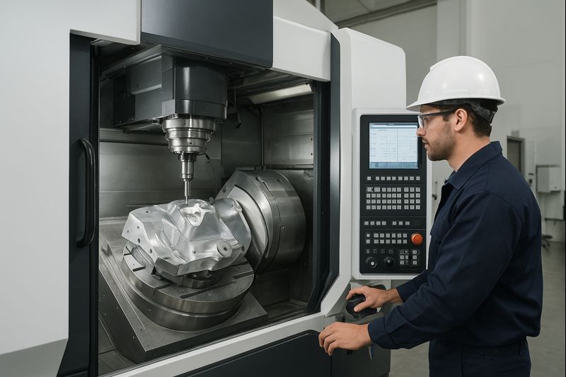
What Are the Five Axes of a 5-Axis Machining Center?
The “five axes” of a 5-axis machining center refer to five degrees of freedom that allow the cutting tool or workpiece to move and rotate simultaneously in different directions. These axes typically include:
✅ Three Basic Linear Axes (Same as a 3-Axis Milling Machine)
- X-axis — Left–right movement
- Y-axis — Front–back movement
- Z-axis — Up–down movement
These three axes control the tool’s position in three-dimensional space.
✅ Two Additional Rotational Axes (A, B, or C)
- A-axis — Rotation around the X-axis
- B-axis — Rotation around the Y-axis
(Sometimes the C-axis—rotation around the Z-axis—is used instead. Most 5-axis machines use two of these rotational axes.)
📌 Common 5-Axis Configurations
Different manufacturers and models use different structures. Common configurations include:
① Trunnion Table (Rotary + Tilting Table)
- A-axis: Table tilts around the X-axis
- B-axis: Table rotates around the Y-axis
➡️ Suitable for large or heavy workpieces
② Tilting Spindle Head
- A-axis: Spindle head tilts around the X-axis
- C-axis: Spindle head rotates around the Z-axis
➡️ Ideal for complex parts requiring high angular flexibility
🛠 What Can a 5-Axis Machine Do?
Compared with traditional 3-axis machining, 5-axis machining provides two additional angular degrees of freedom, enabling:
✔ Machining complex surfaces in a single setup
✔ Reduced workpiece re-clamping
✔ Improved accuracy and productivity
✔ Optimized tool orientation and collision avoidance
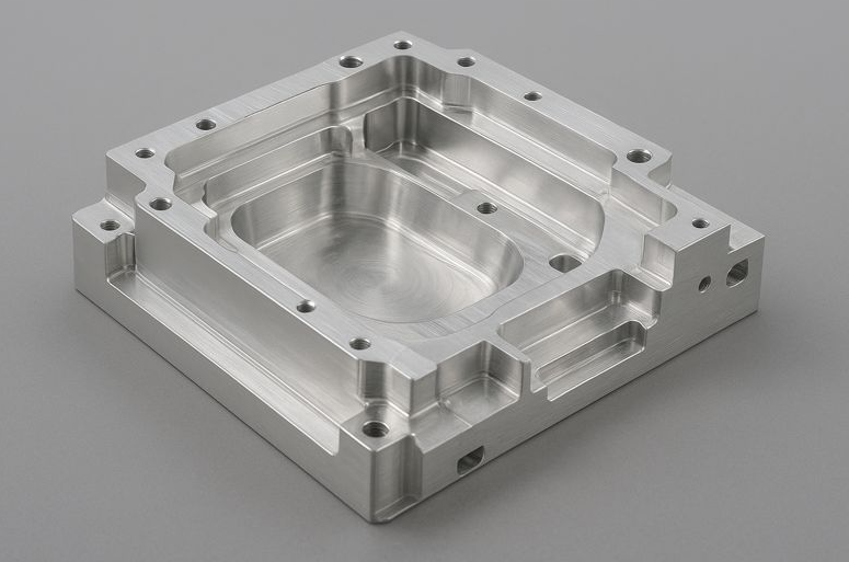
1. Role and Characteristics of Aluminum Parts in Semiconductor Equipment
📌 Common Application Components
- Vacuum Chambers
- Wafer Carriers / Chuck Bases
- Frames / Brackets
- Gas Distribution Plates
- Masks, Covers, Heat Dissipation Structures
📌 Why Aluminum Alloys Are Widely Used in Semiconductor Equipment
| Requirement | Aluminum Alloy Advantage |
|---|---|
| High Precision | Easily achieves micron-level machining |
| Lightweight | Reduces equipment inertia |
| Thermal Stability | Rapid heat dissipation |
| Vacuum Compatibility | Low outgassing |
| Corrosion Resistance | Suitable for surface treatment |
2. Common Aluminum Material Grades for Semiconductor Equipment
✅ Specified Grades (Very Important)
- 6061-T6 (Semiconductor Grade)
- 6063 / 6082 (Structural Components)
- MIC-6 / ALCA-5 (Stress-Relieved Plates)
📌 Key Focus for Semiconductor Aluminum Parts:
Not “strength,” but low internal stress + high purity + controlled deformation
3. Key Value of 5-Axis Machining for Semiconductor Aluminum Parts
🔑 Why 5-axis machining is almost always required for semiconductor aluminum parts:
1️⃣ Complex Vacuum Structures
- Multi-surface sealing grooves
- O-ring grooves (high flatness)
- Internal curves and gas channels
2️⃣ Angled / Multi-directional Holes
- Gas inlet holes
- Sensor holes
- Threaded holes at different angles
3️⃣ Single Setup Requirement
- Setup errors = vacuum leakage risk
- 5-axis machining allows multiple surfaces in a single setup
4. 5-Axis Machining Process for Semiconductor Aluminum Parts
1️⃣ Pre-Processing (DFM / DFM+)
- Confirm vacuum surfaces and sealing surfaces
- Define critical surfaces
- Set reference surfaces and clamping directions
- Reserve material for surface treatment compensation
📌 Semiconductor Aluminum Parts: define “surfaces that cannot fail” first
2️⃣ 5-Axis CAM Strategy (Key Points)
- Mainly 3+2 positioning
- 5-axis simultaneous used locally (curved surfaces, chamfers)
- Fixed tool orientation to avoid uneven surfaces
👉 Semiconductor equipment ≠ aerospace aesthetic parts
👉 Stability > fancy tool paths
3️⃣ Fixture Design (Fixture Engineering)
- Custom aluminum fixtures (same material for thermal expansion match)
- Vacuum suction or low-stress clamping
- Protect reference surfaces (no damage allowed)
📌 Most semiconductor aluminum parts require custom fixtures
4️⃣ Rough Machining (Stress Control)
- Material removal in sections
- Symmetrical left-right machining
- Avoid excessive single-sided cutting
Purpose:
Reduce residual stress → prevent deformation
5️⃣ Intermediate Stress Relief (Critical Difference)
- Common for semiconductor-grade parts:
- After rough machining → artificial aging / natural aging
- Then semi-finish and finish machining
📌 This step is absent in general industrial parts
6️⃣ Finish Machining (Vacuum-Grade Standard)
- Sealing surface flatness: ≤ 0.01 mm
- Surface roughness:
- Sealing surfaces Ra ≤ 0.8 μm
- Non-sealing surfaces Ra ≤ 1.6 μm
- Use new tools
- Low cutting depth
- Stable temperature control
7️⃣ Holes / Channels / Threads
- 5-axis positioned machining for angled holes
- Control burrs (Particle Control)
- Chamfer consistency before tapping
8️⃣ Deburring & Cleaning (Semiconductor Critical)
- 5-axis automatic chamfering
- Manual filing prohibited
- Ultrasonic cleaning
- DI water rinse
- Cleanroom packaging (Class 1000 / 100)
9️⃣ Surface Treatment (Semiconductor Spec)
- Common specs:
- White anodizing (Sulfuric / Oxalic)
- Hard anodize
- Electroless nickel (EN-P, low phosphorus)
📌 Post-treatment checks:
- Dimensions
- Coating thickness
- Hole position variation
5. Quality Inspection & Documentation (Critical for Equipment Vendors)
- CMM full-size measurement
- Vacuum leak testing
- Surface roughness report
- Material certificate (aluminum grade)
- Process flow / inspection report
6. Key Factors for Successful Semiconductor Aluminum Part Machining
✅ Single setup
✅ Stress control
✅ Particle management
✅ Cleaning and packaging
✅ Complete documentation
Semiconductor aluminum parts are not just “finished after machining”; success is defined by whether they can be installed into equipment and enter the process.
5-Axis Machining Process for Aluminum Alloys
From a practical manufacturing perspective, the following outlines a common and well-established 5-axis machining process for aluminum alloys, suitable for high-precision applications such as aerospace, semiconductor equipment, automotive, and optical components.
🔧 I. Material Selection (Common Aluminum Alloys)
Depending on the application, commonly used aluminum alloys include:
| Aluminum Alloy | Characteristics | Typical Applications |
|---|---|---|
| 6061-T6 | Good overall properties, excellent machinability | Structural parts, equipment components |
| 7075-T6 | High strength, harder material | Aerospace, load-bearing parts |
| 5052 | Excellent corrosion resistance | Sheet metal, enclosures |
| MIC-6 / ALCA-5 | Stress-relieved | Precision platforms, fixtures |
📌 6061 and 7075 are most commonly used for 5-axis machining, balancing machinability and rigidity.
⚙️ II. Overall 5-Axis Machining Workflow
1️⃣ Process Evaluation & Machining Strategy Planning
- 3D model analysis (freeform surfaces, chamfers, angled holes)
- Determine simultaneous 5-axis or 3+2 positional machining
- Define datums and machining orientations
- Evaluate tool interference and tool overhang
👉 Key advantage: Multi-face machining in a single setup
2️⃣ CAM Programming (5-Axis Toolpath Planning)
Common CAM software:
- Siemens NX
- Mastercam
- PowerMill
- HyperMill
Key CAM considerations:
- Tool orientation control (collision avoidance)
- Constant Z / constant stepover / flowline strategies
- Optimal cutting angle to reduce aluminum built-up edge
3️⃣ Fixturing & Workholding
Special considerations for aluminum:
- Avoid excessive clamping force to prevent deformation
Common solutions:
- Vacuum fixtures
- Soft jaws
- Customized 5-axis fixtures
📌 Single setup with multi-angle machining is standard in 5-axis processing
4️⃣ Rough Machining
Objective: Rapid material removal without deformation
- Tools: Large-diameter end mills, corner-radius cutters
- Strategies:
- High-speed machining (HSM)
- Adaptive / dynamic milling
Indicative cutting conditions:
- High spindle speed
- Medium to high feed rate
- Shallow depth of cut
🛠 Aluminum alloys are ideal for high speed and high feed machining
5️⃣ Semi-Finishing
Purpose:
- Correct deformation
- Leave uniform stock for finishing
- Maintain surface accuracy using 5-axis simultaneous control
Typical remaining stock: 0.2–0.5 mm
6️⃣ Finishing
Core precision process
Tools:
- Ball end mills
- Bull-nose cutters
Simultaneous 5-axis machining enables:
- Optimal cutting angle
- Reduced tool marks
Surface roughness:
- Ra 0.8–1.6 μm
- Optical components may achieve even finer finishes
📌 5-axis machining enables side cutting, resulting in superior surface quality
7️⃣ Hole Machining & Chamfering (Multi-Angle)
- Inclined and intersecting holes completed in one setup
- Automatic axis rotation
- High accuracy in coaxiality and positional tolerance
8️⃣ Deburring & Surface Treatment
- Automatic edge-following chamfering with 5-axis tools
- Reduced manual finishing
Post-processing options:
- Anodizing
- Hard anodizing
- Sandblasting + anodizing
- Chromate conversion coating
9️⃣ Quality Control (QC)
- Coordinate Measuring Machine (CMM)
- Surface roughness inspection
- Concentricity, flatness, and angular accuracy checks
🚀 III. Key Advantages of 5-Axis Aluminum Machining
✔ Reduced setups → higher accuracy
✔ Complex surfaces completed in one operation
✔ Simultaneous angled holes and chamfers
✔ Superior surface quality
✔ Significantly reduced cycle time
🧠 IV. Practical Machining Considerations
- Prevent chip accumulation → use high-flow coolant
- Apply anti-adhesion tool coatings (TiB₂ / DLC)
- Control thermal deformation
- Always perform full CAM simulation
#CNC Machining #Precision Machining #Positioning Accuracy #Machining Accuracy #CNC Machine Tools #5-Axis Machining #Precision Parts Machining #Automatic Machining Technology #CNC Machine Tool Accuracy
Loading and Unloading Machine Rails #AI Automatic Stacking Robotic Arm
#Yongyi Technology #Automatic Special Purpose Machine Manufacturing #Automatic Arm Handling and Loading #Automatic Inspection and Assembly
#Robotic Arm Suction Cup Gripper Series #CNC Precision Component Manufacturing #Semiconductor Automation Component Supply #Stainless Steel Aluminum Alloy Carbon Steel Copper Alloy
#Engineering Plastics #Sheet Metal Welding Assembly #Ceramic Quartz Machining #Customized Fixture Design, Manufacturing and Development #Customer Assembly Service
#Slide Table Fine Adjustment System #Digital Microscope #Aluminum Extrusion Trolley #Japan NPM Series Products
#Semiconductor Components #Automation Equipment Components #CNC Machining #Robotic Arm Loading and Unloading #Automatic Loading and Unloading Equipment #Smart Manufacturing #Automated Production Line #Smart Factory #Automation Equipment
#CNC Machining #CNC Precision Machining #Semiconductor Components #Automation Equipment #Precision Components #Robotic Arm #Stainless Steel Machining #Engineering Plastics #Ceramic Processing
Yong Yi Technology
Yong Yi Technology Co., Ltd. logo
Location: No. 188-9, Section 1, Dafeng Road, Tanzih District, Taichung City, Taiwan 42756, China
Call: +886-4-25341382
Ring Volume: +886-4-25341847
Email: yongyi-sales@umail.hinet.net
Email: justinwu6767@gmail.com
Post Author